


W-BS/S concrete screw with countersunk head
CONCSCR-(W-BS/SK)-(A2K)-TX40-15-35-8X80


Register now and access more than 125,000 products
- For anchorage in concrete and masonry
- Up to three effective anchorage depths for extremely flexible application (size 6-10)
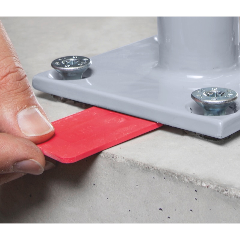
- Fastening can be adjusted up to twice after installation (size 6-10), for example in order to align railings or anchor plates (please refer to the installation instructions)
- Very high loads
- Very low spacing and edge distances due to very low expansion effect
- Very fast and simple installation and immediate load-bearing capacity
- Attractive, flush-mount installation possible
European technical assessment ETA-16/0043 for single fixing point, option 1, cracked and uncracked concrete:
- Static and quasi-static action (∅6-∅10)
- Seismic action, performance category C1 (∅6-∅10) and C2 (∅8-∅10)
- Fire resistance R30, R60, R90, R120
European technical assessment ETA-23/0196 for anchorage in masonry
- Static and quasi-static action (dia. 5-10)
- Fire resistance R30, R60, R90, R120 (dia. 5-6)
European technical assessment ETA-16/0128 for anchors in a redundant non-structural system:
- Cracked and uncracked concrete, (∅5 and ∅6)
- Hollow-core prestressed concrete slabs C30/37 - C50/60, (∅6)
- Fire resistance R30, R60, R90, R120
DIBt National technical approval/general type approval Z-21.1-2075 as bonded screw anchor for anchorage in concrete (∅10), type SK countersunk head
- Use in combination with WIT-BS injectable mortar as WIT-BS bonded screw anchor
- In reinforced and non-reinforced and cracked and uncracked concrete C20/25 to C50/60
Fire resistance period when exposed to fire in accordance with the standard time-temperature curve in masonry (Mz, KSL, KS) and steel-reinforced concrete, (∅5 and ∅6) - expert report no 2101/173/18 - 2018
From size 8, we recommend the use of a suitable tangential impact screwdriver for installation. The recommended maximum rated torque must be observed. When used in masonry, the stone-specific installation data in accordance with ETA-23/0196 must be observed.
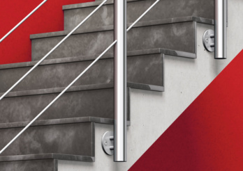
Railings
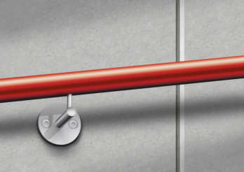
Handrails
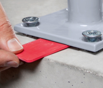
Adjustment - subsequent aligning possible
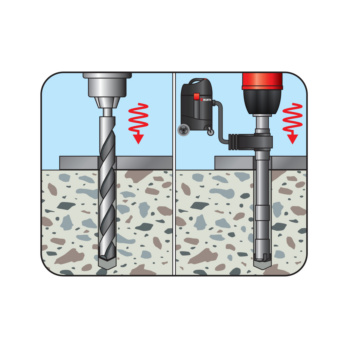
Create the drill hole
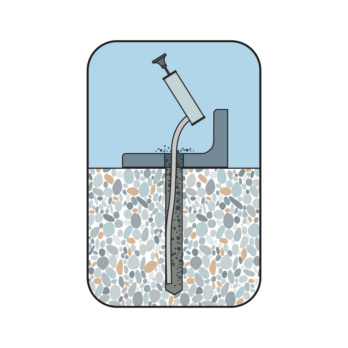
Clean the drill hole
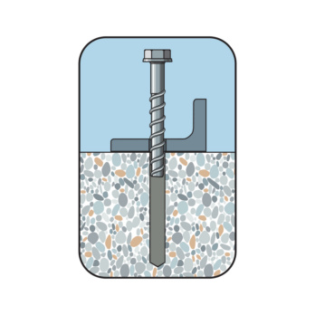
Place screw
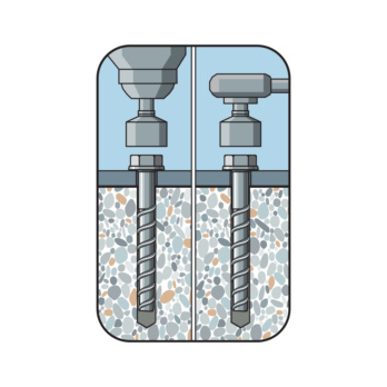
Screw in the screw
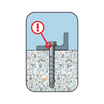
Considered installed when the head is close fitting
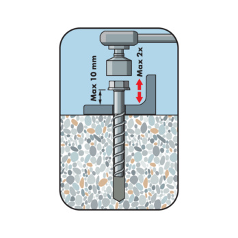
Screw out the screw max. 2x each by max. 10 mm. Underlay. Screw in
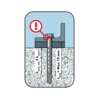
Considered installed when the head is close fitting. Lining max. 10 mm. The required embedment depth must be maintained as a minimum
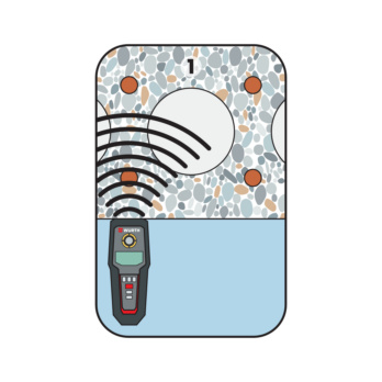
Locate the tensioning strand
Mark the tensioning strand and locate the next one
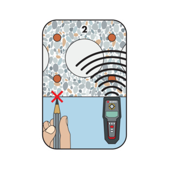
Mark the tensioning strands. Specify the drilling range
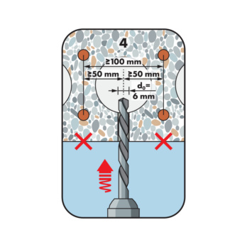
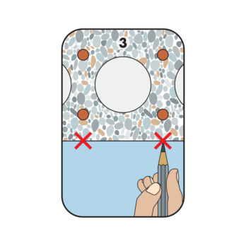
Create the drill hole. Observe spacing
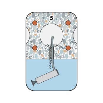
Clean the drill hole
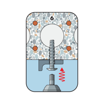
Screw in the screw
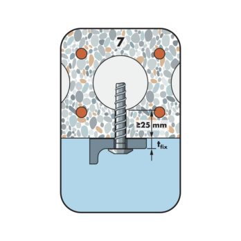
Considered installed when the head is close fitting. Observe the embedment depth/mirror thickness
European technical assessment ETA-16/0043 for single fixing point, option 1, cracked and uncracked concrete:
- Static and quasi-static action (∅6-∅10)
- Seismic action, performance category C1 (∅6-∅10) and C2 (∅8-∅10)
- Fire resistance R30, R60, R90, R120
European technical assessment ETA-23/0196 for anchorage in masonry
- Static and quasi-static action (dia. 5-10)
- Fire resistance R30, R60, R90, R120 (dia. 5-6)
European technical assessment ETA-16/0128 for anchors in a redundant non-structural system:
- Cracked and uncracked concrete, (∅5 and ∅6)
- Hollow-core prestressed concrete slabs C30/37 - C50/60, (∅6)
- Fire resistance R30, R60, R90, R120
DIBt National technical approval/general type approval Z-21.1-2075 as bonded screw anchor for anchorage in concrete (∅10), type SK countersunk head
- Use in combination with WIT-BS injectable mortar as WIT-BS bonded screw anchor
- In reinforced and non-reinforced and cracked and uncracked concrete C20/25 to C50/60
Fire resistance period when exposed to fire in accordance with the standard time-temperature curve in masonry (Mz, KSL, KS) and steel-reinforced concrete, (∅5 and ∅6) - expert report no 2101/173/18 - 2018
Datasheets(X)

Anchorages in concrete, single fixing point with approval (∅6-∅10): In normal weight concrete C20/25 to C50/60 (cracked and uncracked concrete)
Anchors in a redundant non-structural system in concrete, with approval:
- In normal weight concrete C20/25 to C50/60 (cracked and uncracked concrete), (∅5 and ∅6)
- In hollow-core prestressed concrete slabs C30/37 - C50/60, (∅6)
Anchorages in masonry with approval (dia. 5-10):
- In solid sand-lime block and perforated block
- In solid block masonry brick
Specifically designed for surface-flush, visually appealing installation
Suitable for fastening medium to heavy loads in concrete and light to medium loads in masonry:
- Fastening of e.g. staircase railings and balcony balustrades, handrails, steel constructions, wooden substructures, metal profiles etc. in in-place installation
- Fastenings subject to seismic loads in earthquake areas (only concrete)
- Fastenings subject to fire exposure
W-BS/S (galvanised steel) may only be used in dry indoor conditions
For use in concrete < C20/25 and pressure-resistant natural stone (without approval)
Anchor size | 8 mm |
Anchor length (l) | 80 mm |
Attachment height (t fix 1) | 35 mm |
Attachment height (t fix 2) | 25 mm |
Attachment height (t fix 3) | 15 mm |
Thread diameter | 10 mm |
Nominal drill-bit diameter (d 0) | 8.0 mm |
Drill hole depth (h 1.1) | 55 mm |
Drill hole depth (h 1.2) | 65 mm |
Drill hole depth (h 1.3) | 75 mm |
Embedding depth (h nom1) | 45 mm |
Embedding depth (h nom2) | 55 mm |
Embedding depth (h nom3) | 65 mm |
Head diameter (d sk) | 20 mm |
Internal drive | TX40 |
Head type | Countersunk head |
Material | Steel |
Through-hole in the component to be connected (d f) | 12.0 mm |
Surface | Zinc plated |
Type description | W-BS type SK |
| General installation parameters in masonry: | ||||||||||
| Anchor size | Diameter | 5 | 6 | 8 | 10 | |||||
| Nominal length of thread engagement | hnom | hnom1 | hnom1 | hnom2 | hnom1 | hnom2 | hnom1 | hnom2 | ||
| [mm] | 35 | 35 | 55 | 45 | 65 | 55 | 75 | |||
| Nominal drill diameter | d0 | [mm] | 5 | 6 | 8 | 10 | ||||
| Diameter of cutting edges | dcut ≤ | [mm] | 5,4 | 6,4 | 8,45 | 10,45 | ||||
| Drill hole depth | h0 ≥ | [mm] | 55 | 55 | 75 | 65 | 85 | 75 | 95 | |
| Through hole in the fixture | df ≤ | [mm] | 7 | 8 | 12 | 14 | ||||
| Performance data of an individual anchor in solid and perforated block masonry in accordance with ETA-23/0196 | ||||||||||
| Anchor size | Nominal length of thread engagement | Admissible tensile load | Admissible shear load | Min. edge distance | Min. spacing | Distance from joints | Max. torque for manual installation | Max. torque for installation with drill/driver | Installation using tangential impact driver | |
| hnom | Nadm | Vadm | cmin | smin, ||= smin, ⊥ | cj ⊥ ≥ | cj || ≥ | Tinst≤ | Tinst≤ | Timp,max | |
| [mm] | [mm] | [kN] | [kN] | [mm] | [mm] | [mm] | [mm] | [Nm] | [Nm] | [Nm] |
| Solid sand-lime block KS NF in accordance with EN 771-2:2015-11 KS 20 -2.0 - NF - 240 x 115 x 71 mm, stone raw density ρ ≥ 2.0 kg/dm3, stone compressive strength fmean = 26 N/mm2, minimum wall thickness hmin = 240 mm | ||||||||||
| 5 | 35 | 1 | 0,94 | 80 | 80 | 35 | 80 | 6 | 185 | |
| 6 | 35 | 0,89 | 0,94 | 80 | 80 | 35 | 80 | 11 | 10 | 185 |
| 6 | 55 | 1,4 | 0,94 | 80 | 80 | 35 | 80 | 11 | 185 | |
| 8 | 45 | 1,17 | 0,94 | 80 | 80 | 35 | 80 | 27 | 300 | |
| 8 | 65 | 1,23 | 0,94 | 80 | 80 | 35 | 80 | 23 | 300 | |
| 10 | 55 | 1,06 | 0,94 | 80 | 80 | 35 | 80 | 34 | 300 | |
| 10 | 75 | 1,29 | 0,94 | 80 | 80 | 35 | 80 | 146 | 300 | |
| Silka XL solid sand-lime block KS 12DF in accordance with DIN EN 771-2:2015-11 KS- R (P) -2.0 - 12DF - 498 x 175 x 148 mm, stone raw density ρ ≥ 1.8 kg/dm3, stone compressive strength fmean = 14 N/mm2, minimum wall thickness hmin = 175 mm | ||||||||||
| 5 | 35 | 0,66 | 0,91 | 80 | 80 | 40 | 80 | 6 | ||
| 6 | 35 | 0,66 | 0,91 | 80 | 80 | 40 | 80 | 10 | 10 | |
| 6 | 55 | 1,17 | 2,37 | 80 | 80 | 40 | 80 | 10 | 185 | |
| 8 | 45 | 1,8 | 0,91 | 80 | 80 | 40 | 80 | 25 | 300 | |
| 8 | 65 | 1,8 | 2,14 | 80 | 80 | 40 | 80 | 25 | 300 | |
| 10 | 55 | 1,83 | 1,69 | 80 | 80 | 40 | 80 | 45 | 300 | |
| 10 | 75 | 1,91 | 2,44 | 80 | 80 | 40 | 80 | 45 | 300 | |
| Hollow sand-lime block KS L, 3DF in accordance with DIN EN 771-2:2015-11 SWKV KSL 12 - 1.6 - 3DF - 240 x 175 x 113 mm, stone raw density ρ ≥ 1.5 kg/dm3, stone compressive strength fmean = 17 N/mm2, minimum wall thickness hmin = 175 mm | ||||||||||
| 5 | 35 | 0,31 | 0,46 | 58 | 80 | 35 | 58 | 6 | 8 | 100 |
| 6 | 35 | 0,31 | 0,46 | 58 | 80 | 35 | 58 | 11 | 10 | 100 |
| 6 | 55 | 0,31 | 0,46 | 58 | 80 | 35 | 58 | 11 | 100 | |
| 8 | 45 | 0,46 | 0,46 | 58 | 80 | 35 | 58 | 27 | 200 | |
| 8 | 65 | 0,46 | 0,46 | 58 | 80 | 35 | 58 | 27 | 200 | |
| 10 | 55 | 0,63 | 0,63 | 58 | 80 | 35 | 58 | 37 | 200 | |
| 10 | 75 | 0,63 | 0,63 | 58 | 80 | 35 | 58 | 46 | 200 | |
| Masonry brick Mz in accordance with DIN EN 771-1:2015-11 Mz 20 - 2.0 - NF - 240 x 115 x 75 mm, stone raw density ρ ≥ 2.1 kg/dm3, stone compressive strength fmean = 21 N/mm2, minimum wall thickness hmin = 240 mm | ||||||||||
| 5 | 35 | 0,46 | 0,6 | 80 | 80 | 35 | 80 | 2 | 4 | |
| 6 | 35 | 0,46 | 0,6 | 80 | 80 | 35 | 80 | 3 | 9 | |
| 6 | 55 | 0,46 | 0,6 | 80 | 80 | 35 | 80 | 3 | 9 | |
| 8 | 45 | 0,66 | 0,6 | 80 | 80 | 35 | 80 | 16 | 14 | |
| 8 | 65 | 0,66 | 0,6 | 80 | 80 | 35 | 80 | 16 | 14 | |
| 10 | 55 | 0,86 | 0,6 | 80 | 80 | 35 | 80 | 23 | 185 | |
| 10 | 75 | 0,91 | 0,77 | 80 | 80 | 35 | 80 | 23 | 185 | |
| Lightweight concrete solid block Vbl in accordance with DIN EN 771-3:2015-11 Vbl 4 - 1.0 - 2DF - 240 x 115 x 113 mm, stone raw density ρ ≥ 1.5 kg/dm3, stone compressive strength fmean = 4 N/mm2, minimum wall thickness hmin = 240 mm | ||||||||||
| 8 | 65 | 0,17 | 0,66 | 80 | 80 | 35 | 80 | 6 | 10 | |
| 10 | 75 | 0,37 | 0,91 | 80 | 80 | 35 | 80 | 5 | 14 | |
Notes: For further details on compressive strength, edge distances and spacing and installation positions, please refer to ETA-23/0196 To determine the admissible load, the partial safety factor from ETA γM=2.5 was taken into account on the resistance side and a partial safety factor γF=1.4 on the impact side. The specified values apply to an individual anchor in masonry with fvko: 0.15 [N/mm²] and σd: 0.2 [N/mm²]. For combinations of tensile and shear loads, bending moments or reduced edge distances and spacing, please see ETA-23/0196. Documentation for brick removal must also be provided. | ||||||||||
| Performance data in concrete: single fixing point in accordance with ETA-16/0043 | Anchor size [mm] | 6 | 8 | 10 | ||||||
| Nominal length of thread engagement | hnom [mm] | 40 | 55 | 45 | 55 | 65 | 55 | 75 | 85 | |
| Admissible tension load1) on an individual anchor without the influence of the edge distance | Tensile zone (cracked concrete C20/252), s ≥ 3 hef c ≥ 1.5 hef) | Nadm [kN] = C20/252) | 1,0 | 1,9 | 2,4 | 4,3 | 5,7 | 4,3 | 8,0 | 9,6 |
| Compressive zone (uncracked concrete C20/252), s ≥ 3 hef c ≥ 1.5 hef) | 1,9 | 4,3 | 3,6 | 5,7 | 7,6 | 5,7 | 9,5 | 11,9 | ||
| Admissible shear load1) on an individual anchor without the influence of the edge distance | Tensile zone (cracked concrete C20/252), c ≥ 10 hef) | Vadm [kN] = C20/252) | 3,0 | 3,3 | 3,6 | 4,8 | 6,4 | 4,8 | 15,9 | 16,2 |
| Compressive zone (uncracked concrete C20/252), c ≥ 10 hef) | 3,3 | 3,3 | 5,0 | 6,8 | 8,1 | 6,8 | 16,2 | 16,2 | ||
| Admissible bending moment | Madm [Nm] | 4,8 | 12,4 | 26,7 | ||||||
| Admissible load under seismic activity performance categories C1 and C2 see European technical assessment ETA-16/0043 | C1 | x | x | x | x | x | ||||
| C2 | x | x | ||||||||
| For admissible load when exposed to fire (R30, R60, R90, R120), see European technical assessment ETA-16/0043 | ||||||||||
| Installation parameters in prestressed hollow ceiling panels | ||
| Anchor size [mm] | 6 | |
| Minimum spacing | smin [mm] | 100 |
| Minimum edge distance | cmin [mm] | 100 |
| Minimum spacing between the groups of anchors | amin [mm] | 100 |
| Spacing between cavities | lc ≥ [mm] | 100 |
| Spacing between tensioning strands | lp ≥ [mm] | 100 |
| Spacing between tensioning strands and drill hole | ap ≥ [mm] | 50 |
| Nominal drill∅ | d0 [mm] | 6 |
| Through hole in the member being connected | df ≤ [mm] | 8 |
| Installation parameters in concrete | |||||||||||
| Anchor size [mm] | 5 | 6 | 8 | 10 | |||||||
| Nominal length of thread engagement | hnom [mm] | 351) | 351) | 40 | 55 | 45 | 55 | 65 | 55 | 75 | 85 |
| Minimum spacing | smin [mm] | 35 | 35 | 40 | 40 | 50 | 50 | ||||
| Spacing | scr,N [mm] | 81 | 81 | 93 | 132 | 105 | 129 | 156 | 129 | 180 | 204 |
| Minimum edge distance | cmin [mm] | 35 | 35 | 40 | 40 | 50 | 50 | ||||
| Edge distance | ccr,N [mm] | 40,5 | 40,5 | 46,5 | 66 | 52,5 | 64,5 | 78 | 64,5 | 90 | 102 |
| Minimum member thickness | hmin [mm] | 80 | 80 | 80 | 80 | ||||||
| Nominal drill∅ | d0 [mm] | 5 | 6 | 8 | 10 | ||||||
| Dia. of cutting edges | dcut ≤ [mm] | 5,40 | 6,40 | 8,45 | 10,45 | ||||||
| Drill hole depth | h1 ≥ [mm] | 40 | 40 | 45 | 60 | 55 | 65 | 75 | 65 | 85 | 95 |
| Through hole in the member being connected | df ≤ [mm] | 7 | 8 | 12 | 14 | ||||||
| Internal drive | TX25 | TX30 | TX40 | TX50 | |||||||
| Head diameter | dsk [mm] | 12 | 13 | 20 | 22 | ||||||
| Max. rated torque of tangential impact driver | Timp,max [Nm] | 110 | 160 | 300 | 400 | ||||||
| 1) For anchors in a redundant non-structural system | |||||||||||
| Performance data in hollow-core prestressed concrete slabs in accordance with ETA-16/0128 | ||||
| Anchor size [mm] | 6 | |||
| Material thickness [mm] | ≥ 25 | ≥ 30 | ≥ 35 | |
| Anchors in a redundant non-structural system in hollow-core prestressed concrete slabs5) | Fadm [kN] | 0,4 | 0,8 | 1,2 |
| 1) The partial safety factors of the resistances yM regulated in the evaluation/approval and a partial safety factor of the action of γF = 1.4 have been taken into account. For a combination of tensile and shear loads, for the influence of the edge distance and anchor groups, please see the appropriate guidelines e.g. DIN EN 1992-4. 2) The concrete has normal reinforcement. Higher values are possible for higher concrete compressive strengths. 3) The admissible loads were determined without axial influence and the influence of the edge distance. 4) Number of attachment points ≥ 3 and at least one anchor per attachment point produces a load per attachment point of Fadm ≤ 1.4 kN or number of attachment points ≥ 4 and at least one anchor per attachment point produces a load per attachment point of Fadm ≤ 2.1 kN. The admissible loads can be increased if the design shows that the requirements governing the strength and stiffness of the component to be attached remain satisfied even after the failure of an anchor in terms of the limit state of serviceability and load-bearing capacity. 5) The assembly data must be observed. | ||||
| Performance data in concrete: anchors in a redundant non-structural system in accordance with ETA-16/0128 | |||||
| Anchor size [mm] | 5 | 6 | |||
| Nominal length of thread engagement | hnom [mm] | 35 | 35 | 55 | |
| Anchors in a redundant non-structural system in non-load-bearing systems in concrete3) | Nadm [kN] ≥ C20/25 | 0,6 | 0,6 | 3.64) | |
| Admissible shear load1) on an individual anchor without the influence of the edge distance | Tensile zone (cracked concrete C20/252), c ≥ 10 hef) | Vadm [kN] = C20/252) | 2,0 | 2,0 | 3,3 |
| Compressive zone (uncracked concrete C20/252), c ≥ 10 hef) | 2,1 | 2,8 | 3,3 | ||
| Admissible bending moment | Madm [Nm] | 2,5 | 4,8 | ||
| For admissible load when exposed to fire (R30, R60, R90, R120), see European technical assessment ETA-16/0128 | |||||
Last viewed

Tap wrench DIN 1814 Performance, adjustable

Hexagon nut DIN 934, steel I6I/I8I, zinc-plated, blue passivated (A2K)

Pneumatic butterfly impact screwdriver DSS 3/8'' BF

Pan head tapping screw, C shape with H recessed head DIN 7981, steel, zinc-plated black (A2S), shape C, with tip

Hexagon nut, low profile, with clamping piece (non-metal insert) fine thread DIN 985, steel I10I, zinc-plated, yellow chromated (A2C)

Hand tool

Compressed air spray

Twist drill bit HSS DIN 338 type RN 130°

Hexagon bolt with thread up to the head ISO 4017, steel 8.8, zinc-plated, blue passivated (A2K)

System assortment 4.4.1 + 8.4.1 mixed